FINJET H

TECHNICAL SPECIFICATIONS

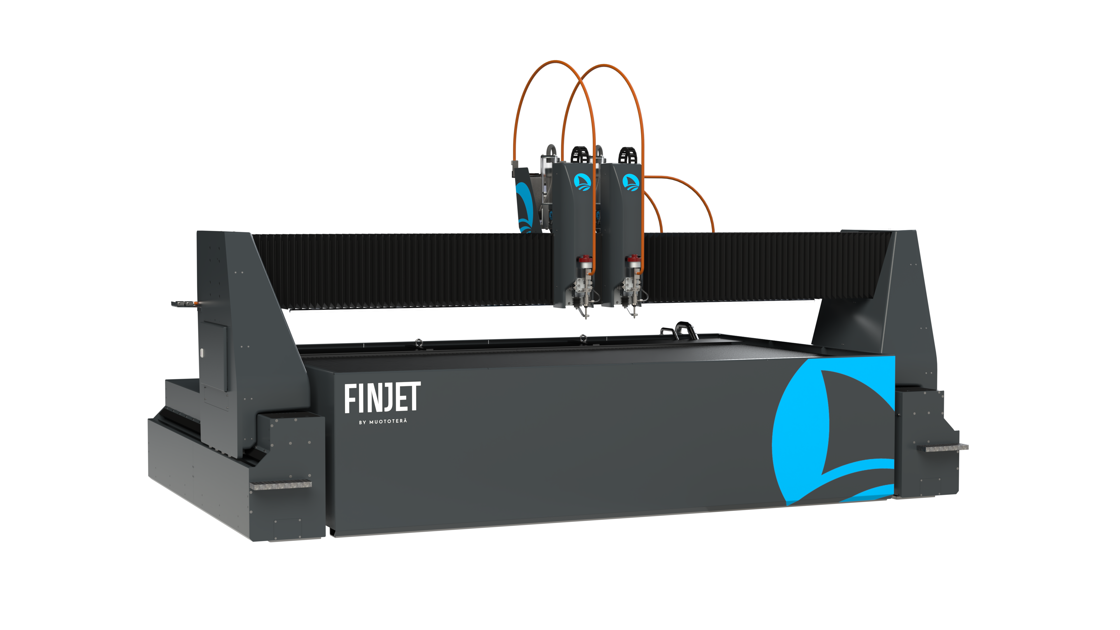
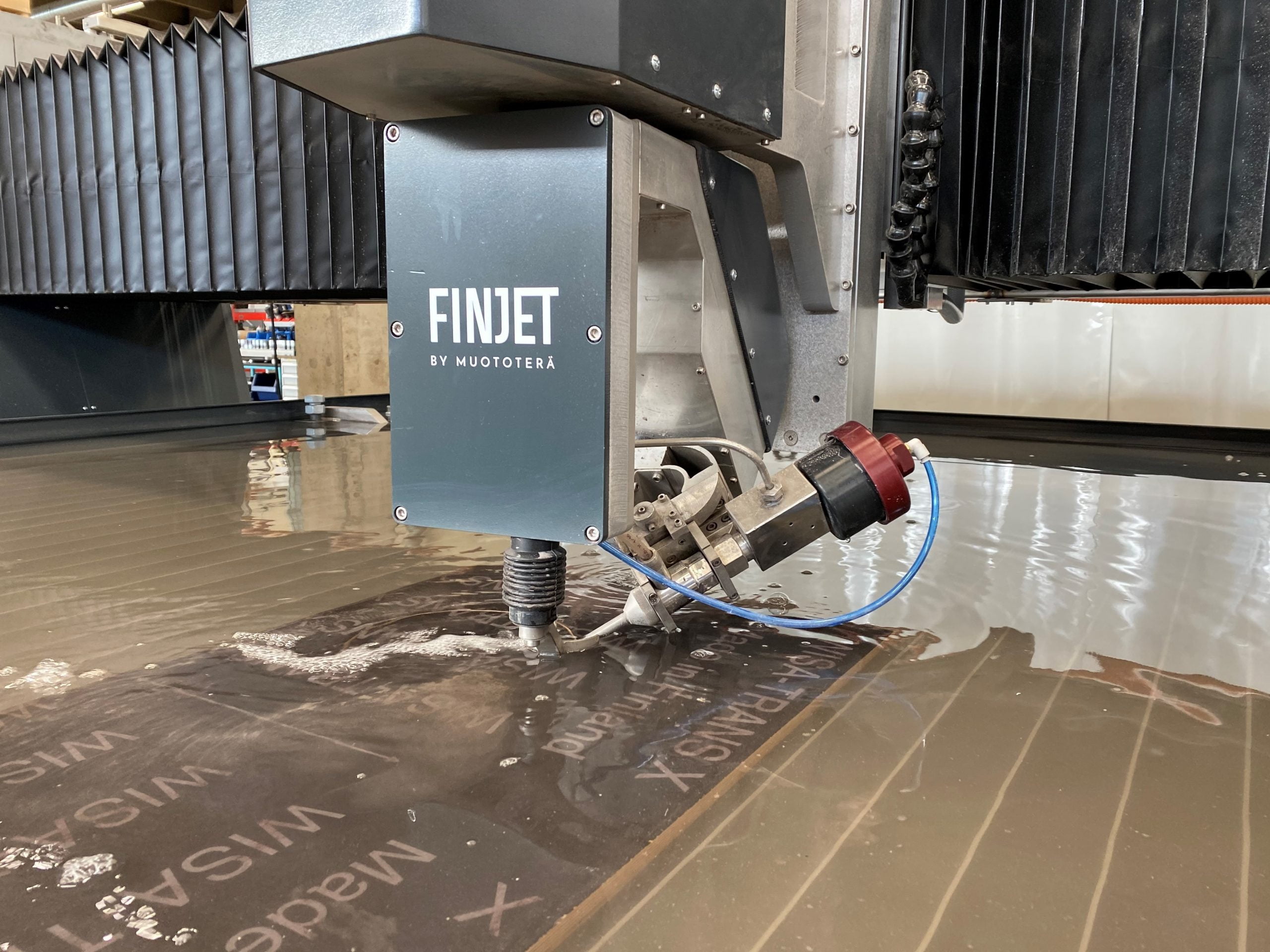
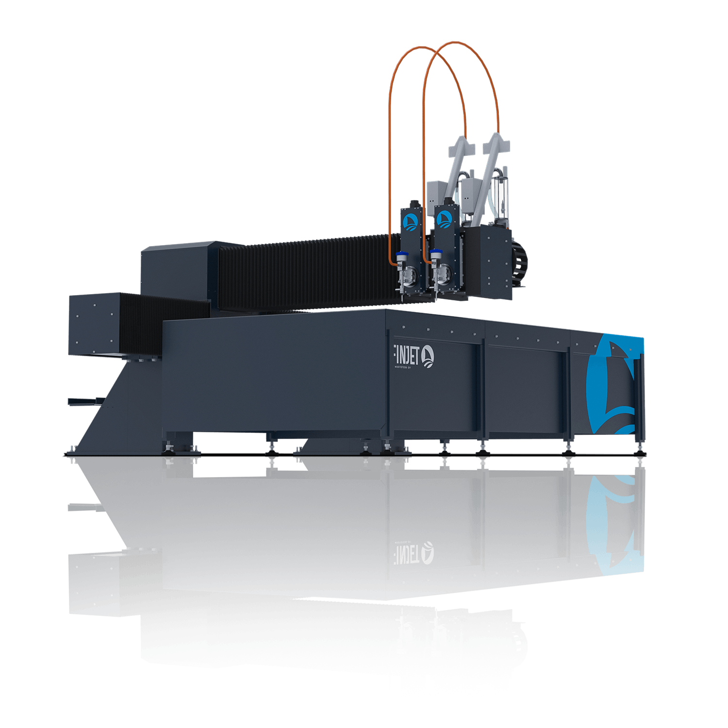
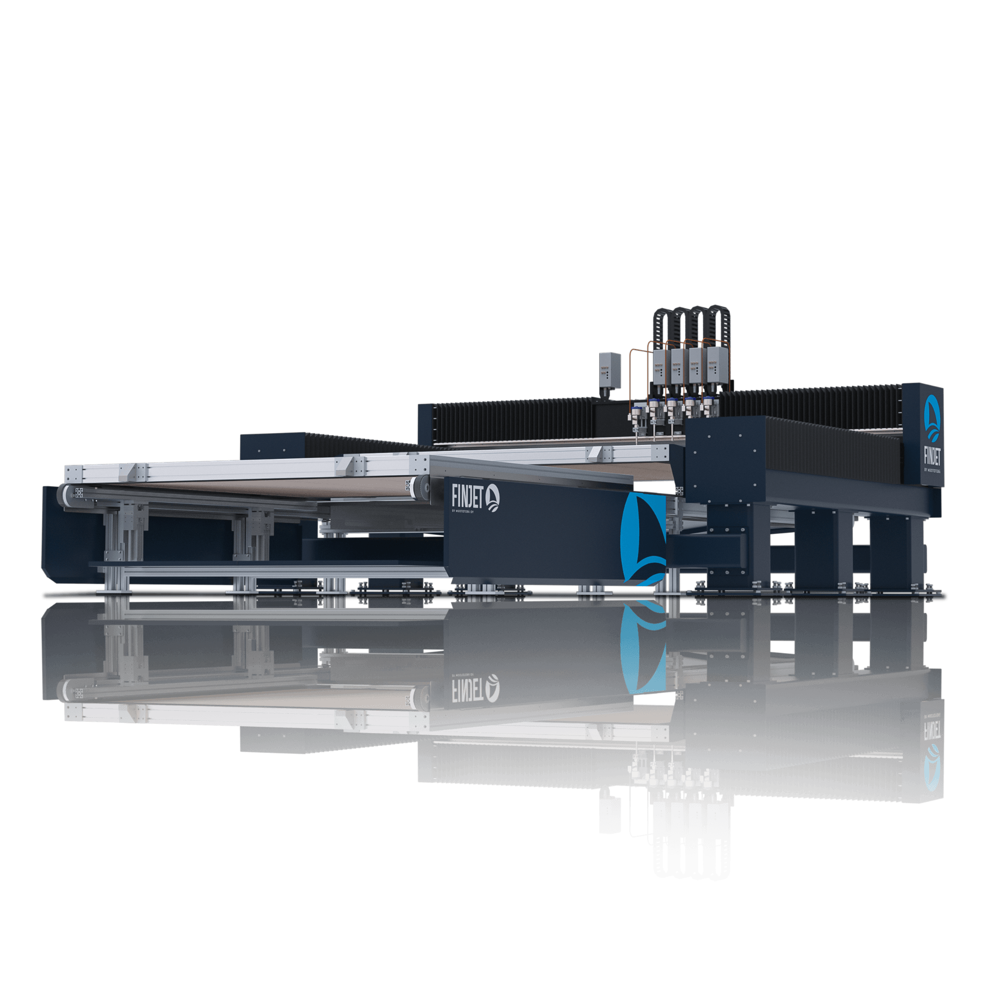
FinJet H-series is designed for continuous heavy duty waterjet cutting. Its modular portal design enables numerous different variations so that every demanding need can be fulfilled. H-series can be equipped with several cutting heads including 5- axis bevel cutting units.

  • Cutting area: 1 x 1 – 4 x 15 m
  • Z-axis: 200 / 300 mm
  • Positioning accuracy: ± 0,025 mm/m
  • Repeatability: ± 0,015 mm
  • X and Y axis max speed: 15 / 40 m/min
  • Cutting heads: 1 – 6, 2D or 3D

FINJET H

MACHINE SOLUTIONS

In the FinJet H -series, special attention has been paid to the mechanical solutions of the waterjet cutting machine. The machine is designed to withstand harsh conditions. No matter how dirty, dusty, dark, humid or variable in temperature the environment might be, the FinJet H is designed to function there and provide the comfort you expect from a waterjet cutting machine.

FINJET H

PROPERTIES

MOVEMENT

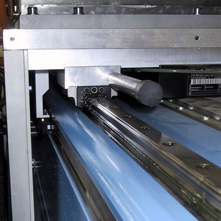
In FinJet H models, movement is executed with Ø 30/40 mm precision ball screws, which achieve a movement speed of 15m / min. High-quality B&R (ABB) servomotors are equipped with absolute measurement, which allows the machine to be started without the need for extra reference run. The bearings of the sleds are always mounted on precision guides with four bearings and at sufficient distances to eliminate vibration. The machine’s mechanics are designed for durability and longevity in all conditions.

The movement can also be done by linear motors. This results in higher speeds (40m or even 100m / min) and accelerations

PROTECTION

Since abrasive waterjet cutting machines are always exposed to at least abrasive and water, protection must be designed accordingly. In FinJet H models, the X-axis is always protected by a tight round bellows. The Y-movement is protected by a tight rubber lip and the machine frame is covered to withstand extreme conditions.

The machine frame is designed so that it can be walked on, if needed, for easy operation and maintenance.

ELECTRICITY & AUTOMATION


Electrical and automation design on all FinJet waterjet cutting machines are planned and executed by Muototerä’s own personnel. This allows optimum compatibility between mechanical and automation components. A good waterjet cutting machine is made from quality components, but it is not enough on its own. All parts must work together seamlessly. The objective of Muototerä is always to make the waterjet cutting machines to perform better than the sum of their parts. In practice, this means collaborative design. In other words, mechanical and automation design are executed simultaneously for best results.

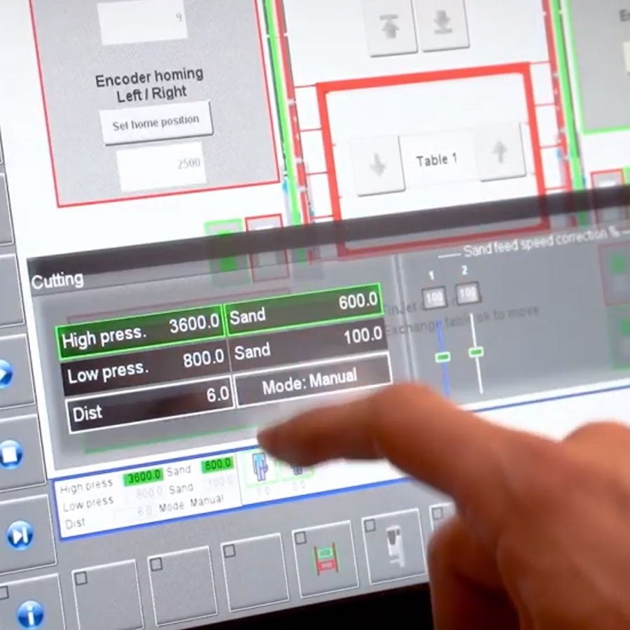
Electric cabinets are always built on FinJet H models with closed-circulation cooling, which makes the electrical and automation components more durable and the waterjet cutting machine less prone to failures. The machine is controlled by Muototerä’s own interface for waterjet cutting. The HMI (Human Machine Interface) is a 21.5 ”Full HD touchscreen with a powerful 1.91GHz processor. The user interface has been designed based on the user experience so that it is simple yet powerful, offering all the features needed for effective waterjet cutting.

HIGH PRESSURE COMPONENTS

High pressure components play a critical role in waterjet cutting. As it is a high pressure device (3800 – 6200 bar), the high pressure components are subjected to extremely heavy stress. In addition to the self-made components, Muototerä uses components from KMT Waterjet. High-quality components guarantee the reliability of the machine at all pressure levels.

All FinJet waterjet cutting machines can be connected to any high-pressure pump, including old ones already at the client’s site. Muototerä is an official distributor of KMT High Pressure Pumps and a Premium OEM Partner. Our high pressure pump product range can be found here

FINJET H

AVAILABLE OPTIONS

Due to the modular design, several accessories and options can also be added as a retrofit.

SAFETY, CONTROL & MACHINE

The cutting table is surrounded with a safety light barrier. Interrupting of light barrier will stop the cutting process and the pump.

Safety light barrier

Isolated cutting area with either fixed walls or mesh fence and sliding door. The cutting table is surrounded with a fence according layout. The fence has one door as standard equipped with safety switch.

Isolated cutting area

Safety dump valve relieves the high pressure water from the tubing of the table when safety circuit is deactivated. At the same time another valve closes the high pressure network allowing to keep the pressure high on the network. Safety dump valve allows the pump to remain on while i.e. changing nozzle without pressure on the machine tubing. This helps to work safely and continue work quickly after activating the safety circuit. Otherwise the pump must be stopped.

Safety dump valve package
It is easily movable and has some place for papers. Dimensions W x D 650 x 750 mm, height 1400mm.

Operator panel on a movable rack
The control panel is fixed to the machine.

Operator panel fixed on the machine
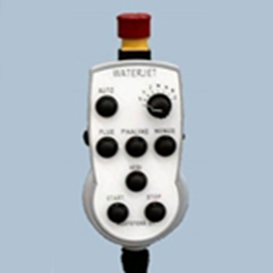
Remote control can be used to position all the axles of the table. It has also start, stop and water test functions.

Remote control
Unit is connected to the controller and it sends a SMS message to preset mobile phone number, when the program ends, or there is a fault with high pressure pump or cutting table. Customer is responsible for ordering a SIM-card. We recommend the mobile unit, if the system will be used for unmanned cutting.

FinMonitor
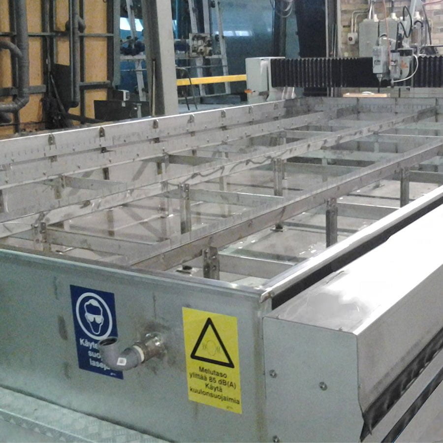
Frame done from stainless steel instead of normal steel.

Stainless steel frame
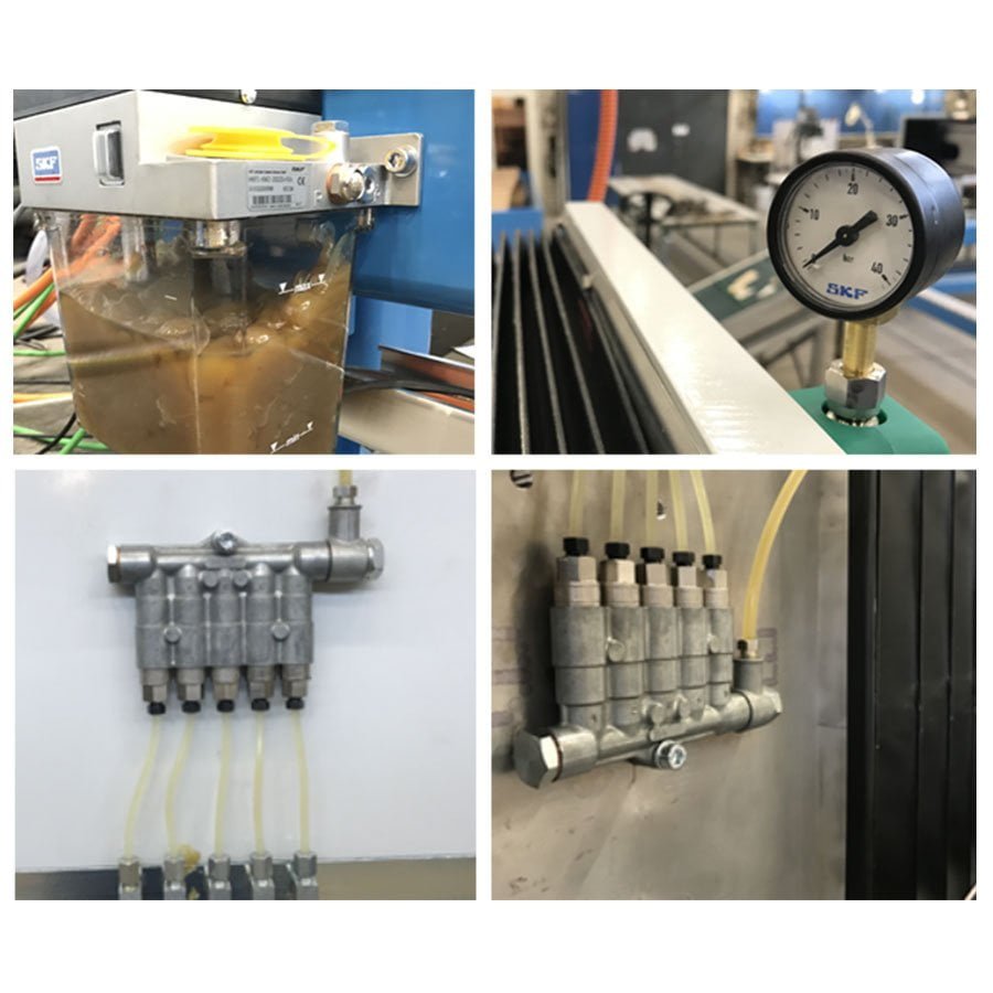
System lubricates all the bearings between programmed time. It is equipped with pressure switch, which assures that the lubrication is working correctly.

Automatic machine lubrication system
As an option ball screws can be replaced by linear motors. This enables faster movements (40m/min) for X & Y –axis. Linear motor comes always with integrated measuring system

linear motors
A separate tube cuttingn unit is installed next to the machine, where the waterjet can be used to cut tubes.

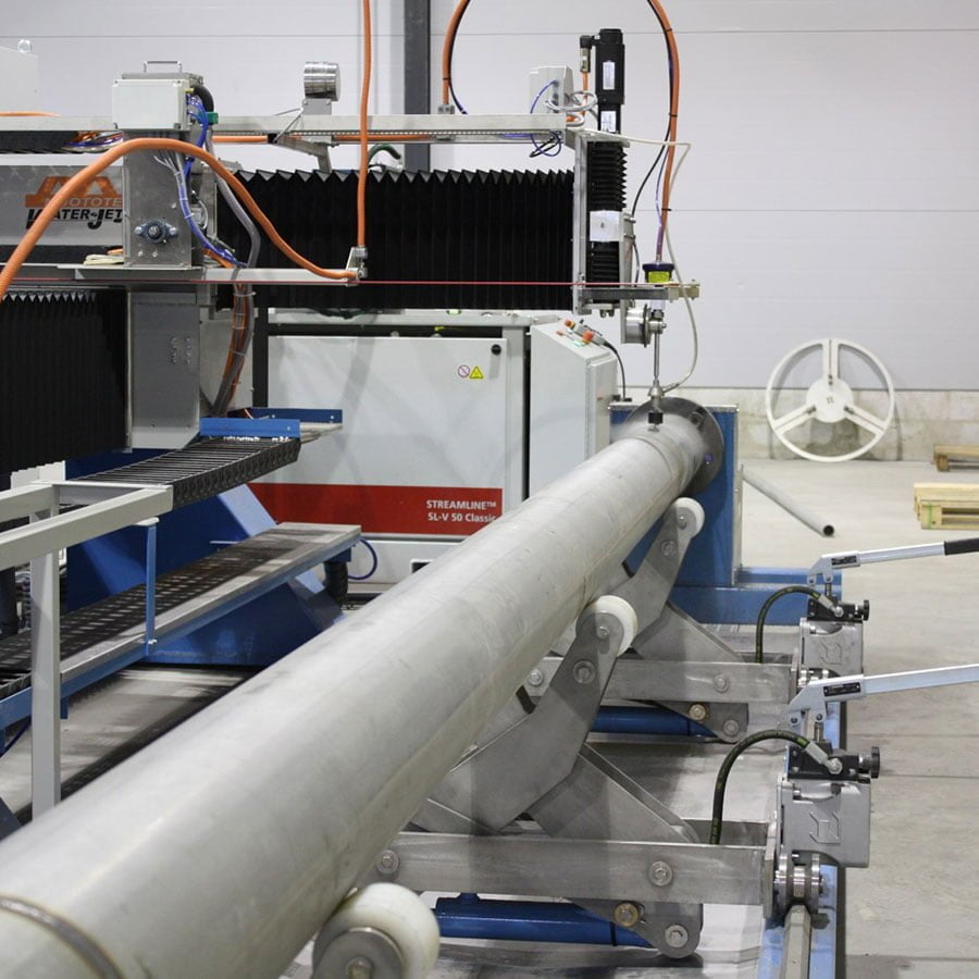
Tube cutting unit

CUTTING TANK & ABRASIVE HANDLING

The system has small volume tank connected to cutting tank. It will adjust the water level through pneumatic air. The additional tank can be removed for cleaning. It has a separate slot in cutting tank to prevent the waste abrasive from flowing to tank. Controlling of water level is made by buttons in control panel.

Underwater cutting
Rubber splash protect in front of the tank can be lifted up by pneumatic air.

Automatically rising cover
On 3 sides of the machine will be installed a stainless steal protector to prevent water splashes from the cutting tank.

Splash prorectors
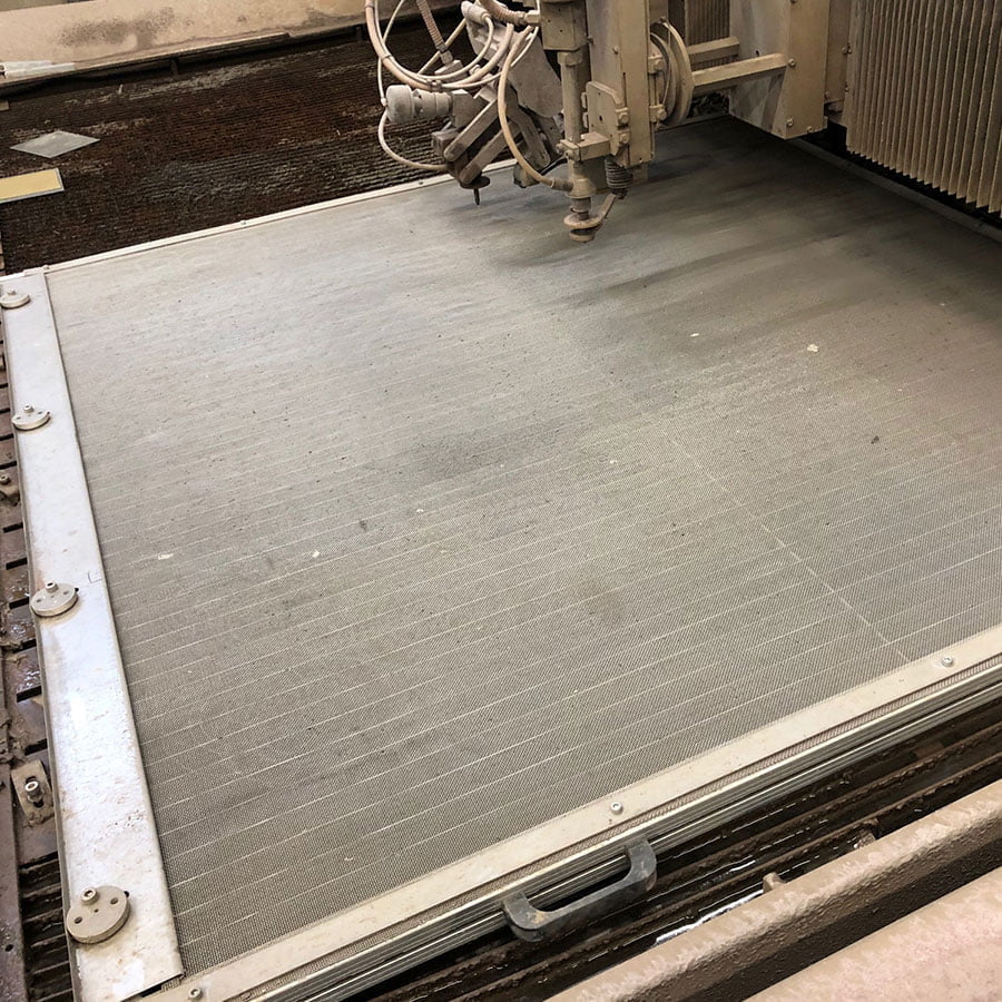
Stainless steel lamellas are recommended for cutting of aluminum and stainless steel.
Stainless steel lamellas
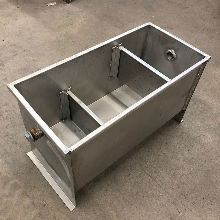
The used cutting water and fine cutting waste are pumped from the bottom of the basin by a submersible pump into the sedimentation basin. From there the water runs through the barriers to the drain.

Steinless steel settling tank
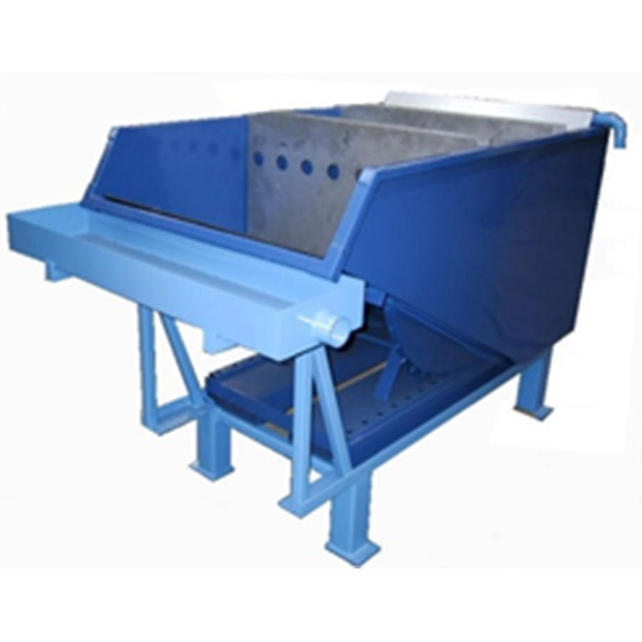
Depending on the size and number of the cutting heads, 18-120 kg/h of abrasive sand is coming into the cutting table tank. The used abrasive and cutting waste is removed from the tank with pneumatic diaphragm pump, which circulates the water through the system.

Abrasive removal system
Movable cutting surface that you can apply when cutting only with water.

Pure water surface
Stainless steel lamellas are recommended for cutting of aluminum and stainless steel. Here also the water jet tank is made out of stainless steel.

Stainless steel cutting tank
Guns make it easy to clean the plate and parts after cutting.

Pneumatic hoses
The sensor in the abrasive feeder monitors the abrasive feed status.

Abrasive feed monitoring
Abrasive will be filled by hand to a pressure silo, which capacity is 200 kg. It give about 8 hours cutting time with one nozzle. Includes the screen. Silo is equipped with low level sensor generating warning message on CNC screen, when abrasive is low.

Abrasive vessel
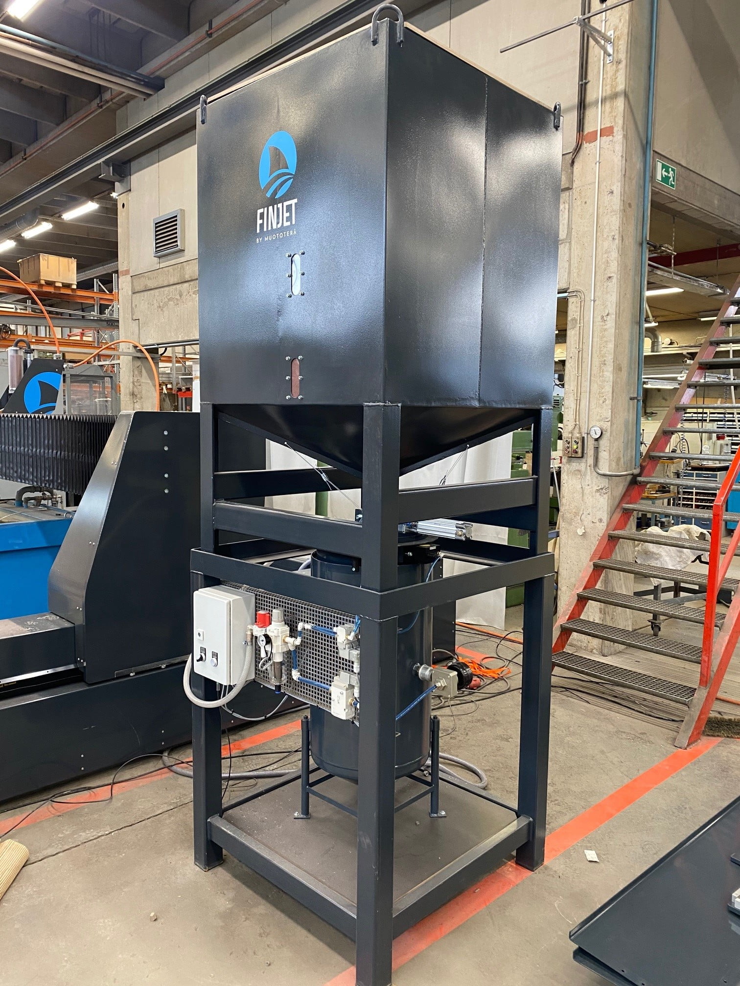
PLC controlled Automatic abrasive silo for easy operation. Easily accessible, the abrasive can be loaded even while cutting. Sensors in lower tank monitor abrasive availability and control lamp shows system’s status. Flashing lamp reminds you to fill up the storage tank.

Abrasive silo

CUTTING HEAD

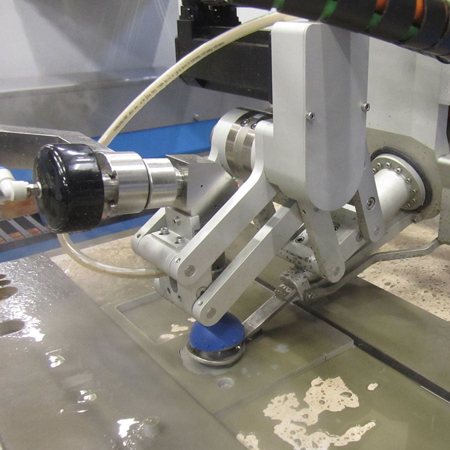
The FinCline 60 allows you to cut beveled pieces. The height sensor comes with the bevel head but cannot be combined with the collision sensor.

FinCline60

The bevel cutting head allows you to cut beveled pieces. The height sensor comes with the bevel head but cannot be combined with the collision sensor.

FinCline45
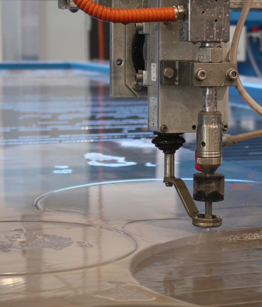
Basic 2D cutting head with three axis (Z, Y, Z).

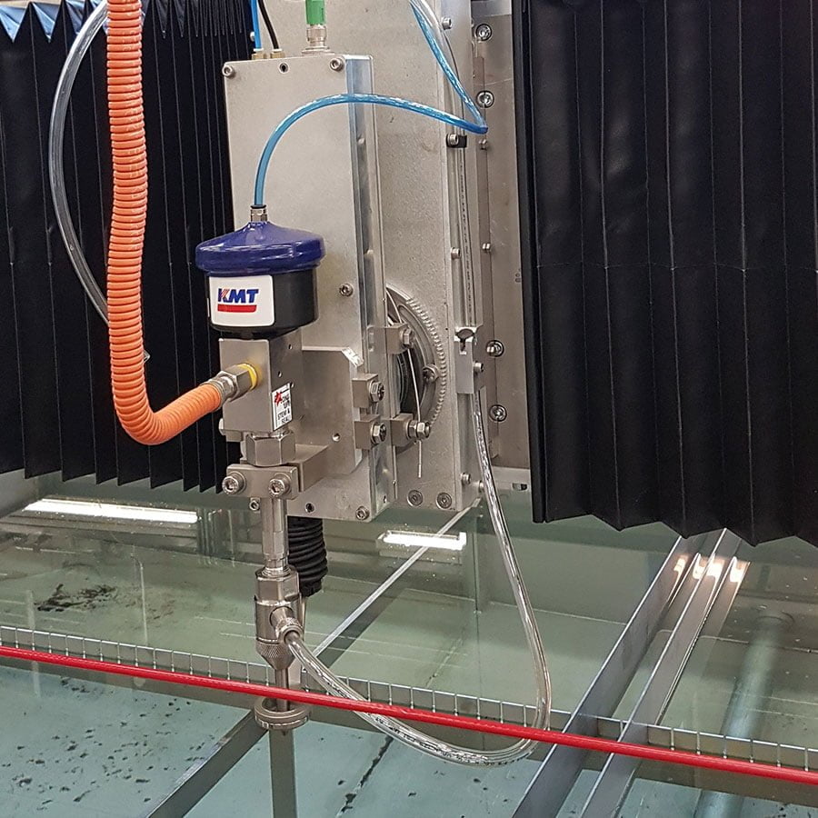
Basic cutting head
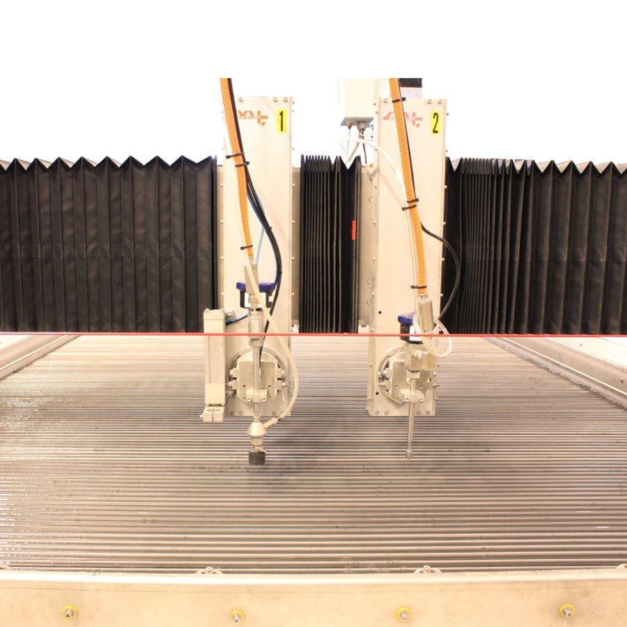
The cutting heads are mounted on their own sleds and the distance between them can be adjusted automatically.

Automatic nozzle distance adjustment
The height sensing device measures the height of the part before piercing and adjusts the nozzle to the correct cutting height.

Height sensor
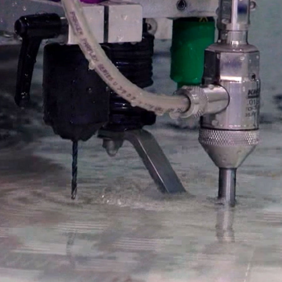
The drill unit allows for penetration and afterwards cutting of materials that are difficult to pierce. Such materials are e.g. glass fiber and carbon fibe. These can be cut without the risk of delamination. The drill unit is exposed by the pneumatic cylinder and is also pneumatic.

Drill unit
The collision sensor protects the nozzle from damage in the event of a collision. In the event of a collision, the magnetic attachment of the nozzle opens and gives a programmatic stop command to the machine. The operation can be resumed by removing the cause of the collision and manually re-inserting the nozzle.

Collision sensor
Enables one sided bevel cutting without the actual 5-axis bevel cutting head.

Manual nozzle rotation
Sapphire crystal protected laser pointer for zero-point setting.

Laser pointer

HIGH PRESSURE PUMP ACCESSORIES

The optional heat exchanger saves tap water when it does not need to be used to cool the pump. The heat exchanger is used to recover the waste heat from the pump for heating the hall.

Oil-air cooler
The tool kit contains special tools required for pump maintenance. The option includes one day maintenance training on delivery of the machine.

Tool kit
Spare part set according to pump and machine type.

Spare parts kit
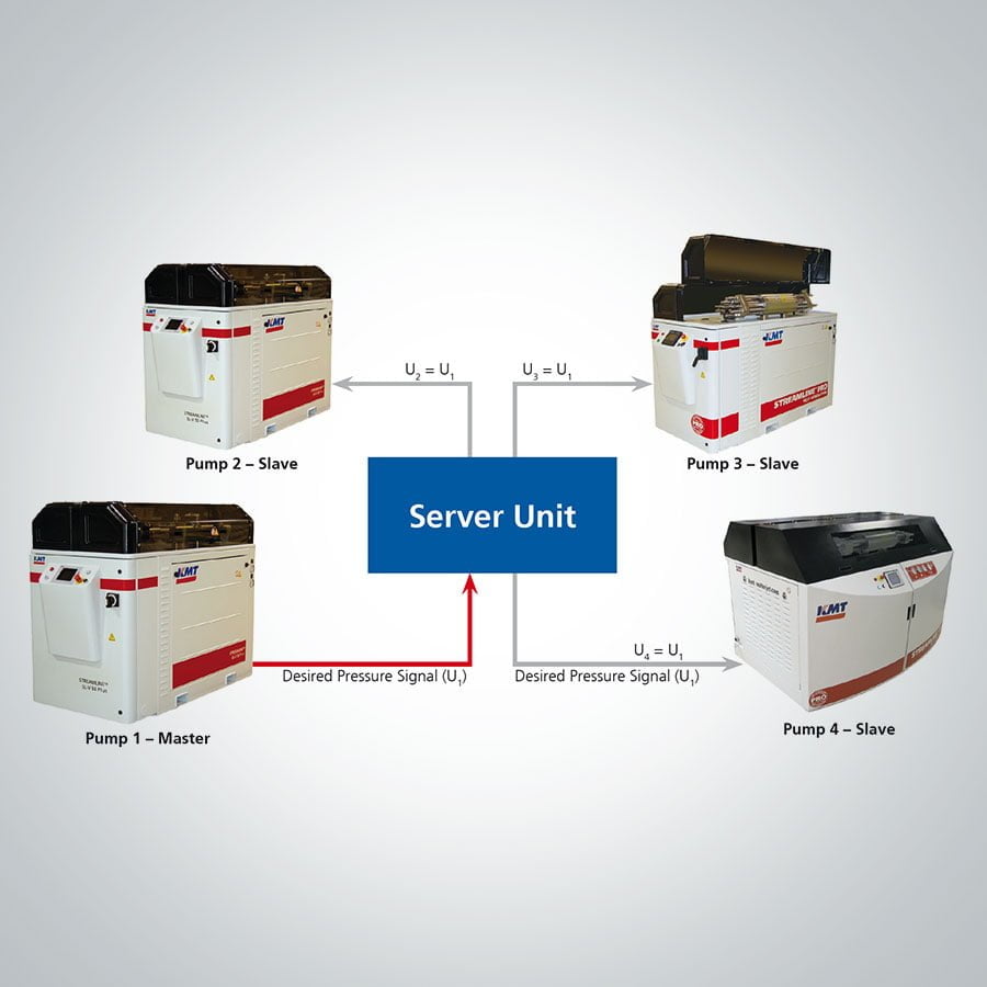
Allows multiple high pressure pumps to operate on the same pressure line.

Stroke control
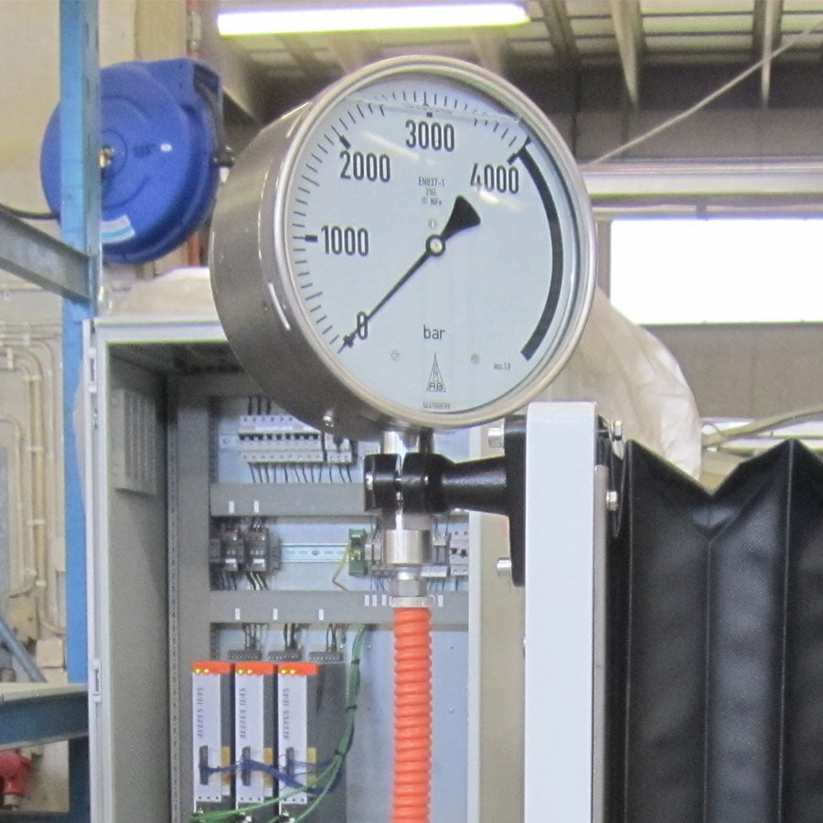
The analog gauge shows the pressure in the pipeline. It also helps to find of internal pump leaks.

Analog pressure gauge
Allows pressure control not only from the pump but also from the machine control.

Pressure display

DESIGN YOUR WATERJET CUTTING MACHINE

Configure your own waterjet cutting machine! Design and request for quote of a waterjet cutting system by choosing the best fit from various options.

H

FinJet L waterjet cutting machine

L

FinJet P waterjet

P

S

FinJet R waterjet

R

FinJet X

X

H

L

P

S

R

X